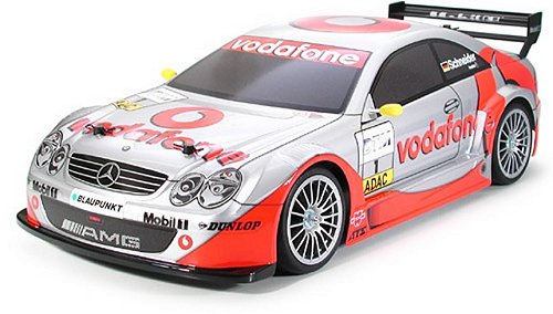
Buying a Used Tamiya Mercedes Benz CLK
Touring Car (and What to look for)
There are essentially three reasons you might want to buy a used Tamiya Mercedes Benz CLK Electric Touring Car; you may be a collector, looking to restore and display it; restore and sell for a profit; or simply restore and race an iconic vintage model. Personally, I used to get a buzz out of restoring an old clapped-out model, installing modern day electrics and maybe a few hop-ups, then showing the gang at our local club, just how competitive those old models could still be.
Cheap, pre-loved bargain models, parts and spares are always coming up for sale, but once you have made your purchase, the one thing you will always need, is an instruction manual. If not supplied with your purchase, they can often be downloaded from the Tamiya website, or purchased separately on eBay. With an instruction manual, any problems with your model Touring Car you may discover, can easily be fixed.
Make a General Visual Inspection
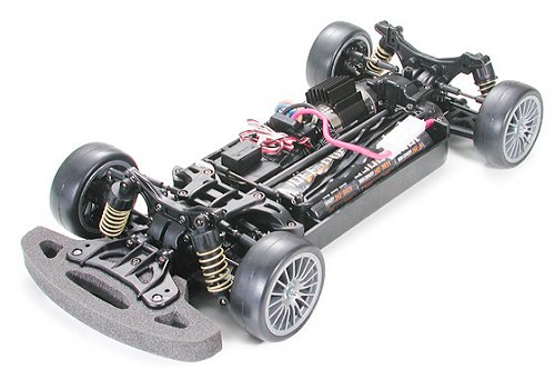
When you receive your used Tamiya Touring Car, make a general visual inspection of the chassis, front and rear wishbones, suspension shock towers etc, for any broken parts that may need to be replaced. Then, take a screwdriver and box spanner and check each self tapping screw and nut for security, taking care not to over tighten.
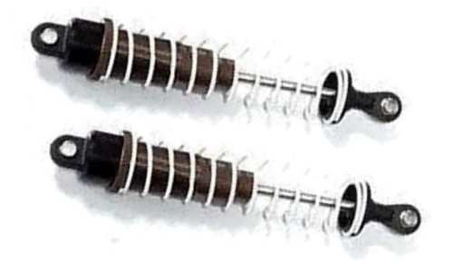
Next, for those Tamiya models with oil filled shock absorbers, remove them from the chassis and dismantle the coil springs. The damper shafts should push in and pull out with a smooth action. If you feel a jolt as you change direction, this means the oil has leaked out and must be topped up. At the same time, change the O-Ring seals to prevent more leakage. Also check the damper shafts for damage. If they are scratched, change them as soon as possible.
Check the Body-Shell
If the body shell of your Tamiya Mercedes Benz CLK is broken, ripped or damaged in any way, this can be easily repaired with rubber solution glue. Also, for added protection and if available for your Mercedes Benz CLK model, fit an under guard to stop dirt and gravel entering the chassis.
Drive Shafts and Turnbuckles
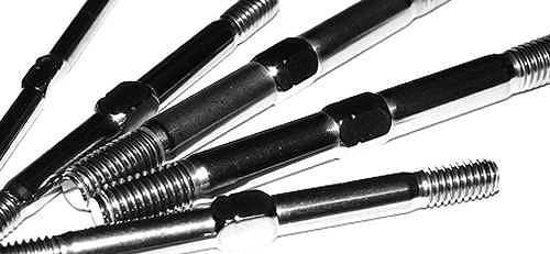
Examine the drive shafts for wear and replace as required. If possible, change them for titanium. The steel shafts wear and bend too easily.
If you intend to race your Mercedes Benz CLK Touring Car model at a competitive level, I would also recommend you obtain and fit titanium pivot shafts, turnbuckles, tie rods and steering rods.
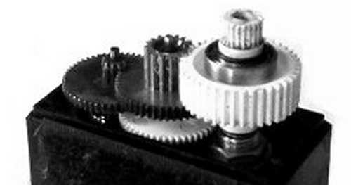
Examine the Drive System
On Belt driven models, the Drive Belts need checking at regular intervals for wear, tension and damage. If deemed necessary, adjust the tensioning pulley until the belt can be depressed in the centre by no more than around 5mm. If the belt was slack, also examine the drive pulleys for wear. The teeth should provide a well seated fit for the belt teeth and not be rounded on the corners. If the belt teeth do not fit snugly, change the pulleys as soon as possible. For top level racing it may be prudent to replace all belts and pulleys after each race meeting.
For Gear driven models, the gearbox of your used Touring Car should be opened up to check for gear wear and lubrication. A thin coat of grease is often used on internal gears and although this is fine for basic running around on the back yard, if you intend to race your Touring Car at a higher level, this should be removed and replaced with racing oil (ZX1 or Teflon Oil). Of course, this should be reapplied after each race meeting.
Pinions and Spur Gears
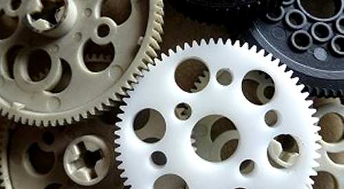
Gears are a weakness on all Touring Car RC models. Head on collisions can easily damage the gear teeth on nylon and plastic spur gears. Heavy impacts can also loosen the nuts or self tapping screws that hold the Electric Motor in Position, allowing the pinion gear to pull out of mesh slightly and rip the tops off the teeth on your spur gear. To minimise this possibility, fit bolts with locking nuts to the Electric Motor mount and remember to check them for security after every two or three runs.
Don't Neglect the Ball-Joints
Ball joints always cause problems. For top level Electric Touring Car racing, the plastic ball connectors should be checked and if deemed necessary, changed after every meeting. A simple thing like a loose fitting connector popping off, could easily end your race, so better safe than sorry.
Steering Servo and Servo-Saver
The Mercedes Benz CLK steering servo is also prone to damage. In high speed crash situations, the fragile gear teeth of the servo can be broken off, rendering your expensive servo useless, so be sure to obtain a good quality "Servo Saver". Check out my Servo Information article.
Stabilizers
If body roll on your Tamiya Mercedes Benz CLK is a problem, handling can be improved with the use of stabilizers, anti roll or sway bars, stiffer tuning springs and, or, thicker silicone oil in the dampers.
Don't Forget those Bearings
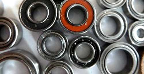
If your used Tamiya Touring Car comes with plastic and sintered brass bushings (ring type bearings), check the shafts that run in them for wear. Dust and grit can get into these bearings and abrade the shafts. Therefore, you should replace them all with shielded ball bearings. If the model has been run with ring type bearings, you may have to change all the axles and driveshafts. For more information, take a look at my article, How to get the best from your Bearings.
Finally, good luck with your Mercedes Benz CLK model and good racing.
▼ Scroll Down for More Articles and Advice ▼
|