Radio Controlled Models
Share RCScrapyard on Facebook
RCScrapyard Radio Controlled Models
Flags
RCScrapyard.net contains Google AdSense Ads and Amazon Affiliate links, from which we may earn commission. See our Disclosure page for more information.
bar

RC Model Car ESC

Electronic Speed Controllers (ESC)
And Soldering Tips

For Radio Controlled Models
RC Model Airplane ESC
Introduction

    Electronic Speed Controllers have been around for a long time now and it seems each new generation of RC enthusiasts are provided more and more choice of size, sophistication and price.

    For newcomers to RC, the article below explains a little about the history of the ESC and provides some basic guidelines of what kind of ESC you may require for your model.


ESC Capacitors ESC Cooling Fans ESC-Motor Combo RPM-Sensors ESC Tester Sensor Cables Servo Tape Battery Packs Battery Chargers
Electric Motors Brushless Motors Pinion Gears Spur Gears Motor Heatsinks Bearings and Bearing Sets Radio Transmitters etc Radio Receivers Servos


Flags


Electronic Speed Controllers

ESC History:


     The first true Electronic Speed Controllers were developed for brushed stock and modified motors in the late 1970s, early 1980s by companies like Tekin in the USA, LRP in Germany and Demon, a London based company in the UK. These bulky and comparatively heavy early ESCs used basic resistors, rheostats, capacitors, transistor switches for stepped acceleration and rectifiers for reverse operation, all crammed together on a simple circuit board. Although they were a vast improvement on the old cumbersome mechanical speedos of the time, they were still very jerky to control and prone to burn out if not carefully managed.

     Throughout the 1980s and 1990s, each year brought improvements and with the help of the new FET (Field Effect Transistors) plus some basic mass produced integrated circuits, miniaturisation and reliability steadily improved. By the mid 1990s, "regenerative breaking" to recharge the battery was developed, long before F1 had KERS (Kinetic Energy Recovery System) and adjustable anti lock breaking was becoming the norm.

     With the introduction of Brushless Motors in the late 1990s early 2000s a new breed of ESC were developed to make the most of the new technology and ever improving Rechargeable Batteries. The latest ESC now use sensors to manage the motor and can be adjusted remotely for different conditions.


ESC for Brushed Motors.


    Basic "Silver Can" Stock Motors that are usually supplied with RC model kits are easily satisfied by low current 5 Amps to 20 Amps ESC. However, Modified Brushed Electric Motors are very power hungry and need lots of Amps to feed on. ESC for these motors range from around 20 Amps to 340 Amps.

    On many older models the setup of the ESC was done using a small screwdriver to adjust the trim and output punch but newer models use a simple one step push button system.

    Higher spec ESC can be programmed to set the acceleration curve and breaking to suit your particular driving style.


ESC for Brushless Motors.


    ESC for Brushless Motors are completely different to those for brushed motors and are not compatible in any way.

    These ESC take the DC (Direct Current) input from the battery and transform it into three phase AC (Alternating Current). The three output "waves" go to each of the three wires on the Brushless motor. By changing the wavelength or frequency of the output wave the motor will spin faster or slower for acceleration and breaking. For reverse, any two of the three "phases" are simply switched.

    Current ratings of Brushless Motor ESC, at the time of this article, can be anything from 3 Amps to around 300 Amps.

    For beginners it is recommended that you buy an ESC and Motor Combo to ensure the Current rating for the ESC is correct for the Motor.


BEC (Battery Eliminator Circuit).


    Many, but not all ESC have BEC to provide power for the Radio System without the need for a separate battery.


Safe and Efficient Soldering


   In the sport of Radio Controlled racing, there are a number of things you have to learn to get you up there with the best. One of the most difficult, for those with little practical skill, is the art of Soldering.

Why Solder?


   For their 540 silver can motors, Tamiya provide two wires, typically green and yellow, soldered to the endbell, with two bullet connectors to plug into the speed controller. While this is fine for bashing around the back yard, as you advance to a higher level you will soon find just how inefficient this method is.

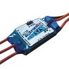
   Motor wires are best soldered directly to the ESC. That way no energy is lost through high current draw. Some of the top drivers at one time even used to solder their batteries directly to the ESC, but these days with connectors such as "Deans" and "Power Pole" this isn't necessary - but I still wouldn't use any kind of connector for the motor.

Use the Right Solder


   There are basically two kinds of solder. Plumbers solder which is made up of 60% Lead and 40% Tin, and Electrical solder, which is the opposite, 40% Lead with 60% Tin. NEVER use plumbers solder for your battery, ESC or motor joints. Lead melts at 327 degrees C, where as tin melts at 232 degrees C. The higher Lead content of plumbers means it melts at a higher temperature, which is not good for your battery cells. Also, Tin has almost half the electrical resistance of lead, so with the higher Tin content of electrical solder, electricity flows much easier to your motor.

Do NOT use Lead Free Solder


   More recently, due to the European regulations for lead use, lead free solders are becoming more widely used - well, in Europe anyway. The problem with lead free is the melting temperature - it is much higher, making it difficult to produce reliable joints.

Be Careful


   Lead, as we know, is a poison to the body if ingested or inhaled in certain quantities, so when using lead based solder, try not to inhale any of the fumes and always wash your hands after completing your work. One of my friends also wears cotton gloves, but I find these cumbersome.

   For me, electrical lead / tin solder is far easier to use, and if used with care, has less potential to damage your batteries having a much lower melting temperature. If you prepare your own Battery Packs, check out my article "Soldering Battery Packs Safely".


^ TOP ^


^ TOP ^


^ TOP ^


Gas/Nitro Engines Body Shells Radio Transmitters etc Tires Wheels/Rims Electronic Speed Controllers Battery Packs / Chargers Electric Motors


RC Models:
Radio
& Motors:
Other
Accessories: