Radio Controlled Models
Share RCScrapyard on Facebook
RCScrapyard Radio Controlled Models
Flags
RCScrapyard.net contains Google AdSense Ads and Amazon Affiliate links, from which we may earn commission. See our Disclosure page for more information.
bar

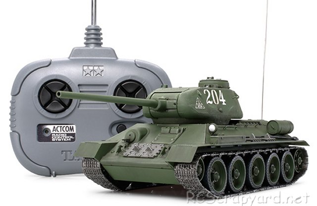
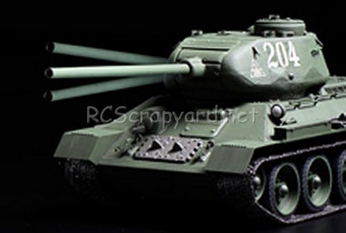
Tamiya Russian Medium Tank T-34-85 - 48208 (Radio Controlled Model Review)

1/35 Scale Electric Tank -

  Released by Tamiya on April 25, 2009, the 1/35 R/C Russian Medium Tank T-34-85 (#48208) came with a 4-channel radio system.

  The gearboxes are loaded at the rear of the chassis which comes pre-assembled with small motors. The included motor features a connector to make wiring less complicated. Additionally, there is only one gearbox to control both the turret rotation and gun barrel elevation.

Tamiya Russian Medium Tank T-34-85 - # 48208

▼ Scroll Down for More Images ▼


  The Russian T34-76 rudely shocked the German Panzer divisions with its arrival and strength which triggered the development of Tiger and Panther tanks. From this, an improved T-34-85 entered the fray with an improved 3-man turret design and a more powerful 85mm gun. In addition, the T-34-85 had a streamlined lighter body and was fitted with a V12 liquid cooled diesel engine which produced 500hp. From the end of 1943 through to June 1945, approximately 29,000 units were produced and together with the T-34-76, they played an active part in driving out the Germans from Russia and continued in service even after the war.


Rating: 44 Stars out of 5 RCScrapyard


Gas/Nitro Engines Body Shells Radio Transmitters etc Tires Wheels/Rims Electronic Speed Controllers Battery Packs / Chargers Electric Motors


Flags


Tamiya Russian Medium Tank T-34-85

Hints, Tips and Information

How to avoid Radio Interference

1/  The first consideration when installing your Receiver into your Electrically Powered Model is to make sure it is well away from the Negative Battery terminal, and the Motor. The Magnetic field can cause stuttering type interference at times of high current draw (i.e., Fast Acceleration)

2/  Make sure the Ariel tube is long enough for the Ariel wire. The tip of this wire is highly sensitive and should be as high, and as far away from the Motor as possible (yup, its that magnetic field prob again)

3/  If all else fails, a simple tip that often works for all RC Model enthusiasts is to wrap the receiver in Aluminium Foil, to shield against any magnetic and external radio interference.

Read the Complete Article  ▶ ▶


Tamiya Buggys Tamiya Trucks Tamiya Monster Trucks Tamiya Rock Crawlers Tamiya Off Road Chassis Types Tamiya Touring Car Tamiya Drift Car Tamiya WRC Car Tamiya M Chassis
Tamiya Tractor Trucks Tamiya Touring Car Chassis Tamiya F1 Tamiya F1/Le Mans Chassis Types Tamiya Military Tamiya Tanks


Hints, Tips and Information

Electric Motors for RC Models

Winds and Turns

Q/  What does 15x2 or 17x3 mean?
A/  The first number relates to the number of times the wires are wound round each of the 3 armature segments, the second number relates to the number of wires side by side. So a 15x2 would have 2 wires laid side by side and wrapped around each segment 15 times.

Q/  What is the difference in performance between a Low Turn motor (eg 11x1) and a High Turn motor (eg 27x1)?
A/  A Motor with Less Turns like an 11x1 means high current draw from the batteries which corresponds to less runtime, but More Power (Torque or Punch) Best for tracks with lots of corners and short straights where fast acceleration is needed. (use a small pinion)
Motors with More Turns like a 27x1 give you More runtime, but Less Power. So you get a smoother response and are therefore easier to drive. Better for less experienced drivers and Long straight, sweeping corner tracks. (with a large pinion). This is correct for Brushed, Modified and Stock Motors as well as Brushless Motors.

Q/  How do the number of winds effect a motor?

Read the Complete Article  ▶ ▶


Information and Advice

Electronic Speed Controllers

History

   ESC were originally developed to be used in conjunction with brushed 27T stock and modified motors in the late 1970s, early 1980s. Compared to modern day Controllers, they were Bulky and heavy, constructed using basic resistors, rheostats, capacitors and transistors, crammed together on a simple circuit board, to provide stepped but smooth acceleration when compared to the old mechanical, servo operated sweeper Speed Controllers. An Electronic Switch to change the direction of current flow was used on some of these early ESC to give reverse operation. Although they were a vast improvement on the old mechanical speedos of the time, they were expensive, jerky to control, and prone to burn out if not carefully looked after.

   As new technology became available, improvements were slowly made, and with the introduction of the new FET (Field Effect Transistors) and some basic mass produced silicon chips, ESC were made smaller and their reliability gradually improved.

   By the mid 1990s, "regenerative breaking" was developed. This meant that energy that would have been lost slowing down the car by effectively turning the motor into a generator, was harvested and put back into the battery. This of course was long before F1 had KERS (Kinetic Energy Recovery System) and adjustable anti lock breaking was introduced.

Read the Complete Article  ▶ ▶


^ TOP ^

RC Models:
Radio
& Motors:
Other
Accessories: